TU Wien, Institut für Flexible Automation
CALINCA
A Compact Autonomous Linkable Intelligent CARRIER
Wolfgang Stubenvoll
Abstract: CALINCA-vehicles are autonomous wheeled mobile transport platforms
for indoor environments intended to execute not only logistic tasks but
also manufacturing processes on the transport platform itself. The special
feature of the CALINCA-vehicles are the small physical dimensions and the
mechanical linkability to form rigid structures of multiple vehicles for
scalability of transport units according to payload weight or payload area.
With this concept a flexible cooperative transport solution for manufacturing
purposes is provided e.g. as an alternative for belt-driven pallets.
INTRODUCTION
Future scenarios of cooperative manufacturing suggest multiple modular
autonomous transport vehicles and autonomous mobile robots (AMR´s) coupling
together and assembling the parts during transport. Rendezvous and docking
of transport vehicles and AMR´s is therefore as important as coordinated
movement of compliant or rigid linked vehicles to reach the goal of cooperative
manufacturing (Levi, 1994).
In case of autonomous mobile robots (AMR´s) cooperation will enhance their
capabilities but it is necessary to add some features and/or to change
their behaviour. A communication between AMR´s is crucial for coordination
of movements.
Research strongly depends on the degree of cooperation which reaches generally
from very losely simple geometrical cooperation to the rigid coupling of
AMR´s. (Ozake et al, 1993) describes the ACTRESS system where a radio communication
system is used to synchronize the motion between the AMR´s without any
link. The COMROS-Project at Stuttgart (Levi, 1994) consists of 3 cooperating
AMR´s Athos, Porthos and Aramis which are based on the same Roboter-platform.
Driving as a convoi and a rendezvous-maneuver with a standing AMR using
communication was the research aim of this project.
Several research projects apply rotatory or translatory joints between
the AMR´s and measure the relative displacement for controlling the positions
relative to the other AMR´s. The METROS-system (Hashimoto and Oba 1993)
consists of AMR´s with a prismatic link including a rotary joint to hold
the transporting object. The Gunryu robots (Hirose, Shirasu and Fukushima,
1996) have a handling arm which is utilized to attach to another Gunryu
robot on the grip stud.
A compliant linkage between two trucks is realized in the OmniMate mobile
robot (Borenstein and Evans, 1997). The linkage has two rotatory and one
translatory axis equipped with sensors to measure the relative displacements
between the two trucks. Each truck has it´s own power supply, motors and
odometry sensors. This is used to correct odometry errors of one truck
by using the other truck as a reference.
The AMR´s Fred and Ginger at Salford (Eustace, 1993) are coupled with a
6 degree of freedom compliant linkage. Each of the two has 2 translatory
and a rotatory linkage of the rigid traverse between them.
Docking of vehicles was already subject of research to position an AMR
relative to a fixed target accurately (e.g. docking terminal for loading/unloading,
another still standing AMR). Vandorpe, (1995) describes a docking procedure
for their AMR LiAS to a docking station and reaches an accuracy of 1cm
side distance and 0,5° in orientation with triaural sonar and visual ranging.
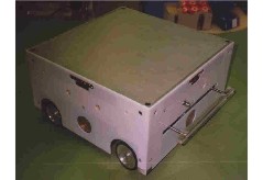
The development of a compact autonomous linkable intelligent carrier (CALINCA)
led to an autonomous transport vehicle that fulfills the mechanical and
electronical preconditions to dock with a rigid linkage to other CALINCA-vehicles
and to move coordinated and synchronized multiple linked CALINCA´s. This
paper describes achieved results in developing the CALINCA hardware-platform.
This will be the basis for further research on rendezvous and docking as
well as communication, realtime task distribution and execution to reach
coordinated movement.
After presenting the concept of CALINCA the mechanics, electronics and
navigation subsystems of a single vehicle focussing on the topics necessary
for docking and linkage are described.
1. CONCEPT
The main concept of CALINCA is the linking of multiple small vehicles to
a larger cluster of rigid coupled vehicles to increase the payload weight
and payload area. It is therefore necessary to have a flat top mounting
and payload area. Linking of many small vehicles forms a large flat payload
area. The four sides of a single CALINCA-vehicle has to fit to a side of
another CALINCA-vehicle with a docking mechanism ensuring not only a withdrawable
rigid mechanical coupling but also a number of electrical connections for
power supply and communication purposes.
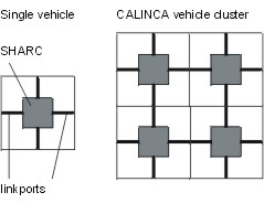
Moving of clusters of vehicles with a rigid coupling need coordination
and synchronization of the steering and driving motions of the single autonomous
vehicles coupled together which is done with communication between the
processors of the vehicles. This is done with high speed communication
linkports of the onboard SHARC DSP capable of 40Mbaud each. Linking of
CALINCA-vehicles forms also a twodimensional multiprocessor-array of DSP´s
(fig.1) and enables parallel processing especially to coordinate navigation,
sonar and motion.
Especially when moving along a bent path requires that each of the wheels
of the vehicles of the cluster has its own correct steering angle dependent
on the centerpoint and the radius of the curve.
To reduce the forces applied to the mechanical docking mechanisms the CALINCA-vehicle
has four wheels with a spring suspension. This guarantees that every wheel
has contact to the ground an can transfer forces (gravitational forces
of the vehicle itself or of the payload).
The development of the CALINCA-vehicle has led to the following characteristics:
l
payload 10 kg
l
minimal payload area 320mm x 320mm
l
net weight 16 kg (8kg storage batteries)
l
height 160mm, ground clearence 10mm (with maximum payload)
l
maximum velocity (flat ground) 0,5m/s
l
maximum climbing gradient 10%
l
battery powered with 12h operation time
l
4 independently steered wheels with spring suspension and encoders
l
2 wheels with independently controllable driving motors
l
indexing capability through 4 inside cones
l
4 docking mechanisms on each side
l
ultrasonic sensors for orientation and collision avoidance
l
navigation with odometry, ultrasonic sensors and stored maps
2. MECHANICS
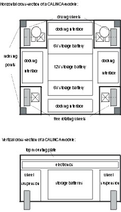
The chassis of the CALINCA-vehicles consists of a top mounting plate, 4
side traverses, 4 wheel suspension units, the driving gear boxes and the
battery holding construction (see fig. 2).
Each wheel suspension unit provides a compliant spring suspension for the
wheel and includes the gear box for the steering worm gear, the indexing
inside cone and the fixing of the steering position sensors the side traverses
and the top mounting plate. The steering gear box is mounted on the chassis
the steering forces are transmitted with a telescopic chock-shaft to the
up and down moving wheel bearings or the driving gear boxes.
The side traverses connect two wheel suspension units on the ends and also
holds the docking interface. It is therefore very easy to enlarge the size
of the vehicle by only increase the length of the side traverses. The shape
and the size of the wheel suspension units and the wheel bearings or the
driving gear boxes remains the same. In case of increased net weight or
payload capacity of the vehicle the wheel suspension units have to be reconstructed
for application of stronger motors.
The top mounting plate can be easy dismounted from the vehicle by only
4 screws. Application specific mechanisms, part holding structures but
also active elements like robot arms can be mounted on the top of a CALINCA-vehicle.
The electronics is situated between the batteries and the top mounting
plate and is easy accessible when the top mounting plate is removed.
2.1 Mechanical docking interface
A rigid connection between two CALINCA-vehicles is established with the
mechanical docking interface. A mechanism was developed using a single
motor only for moving a cone shaped docking bolt into/out of the mechanism
and to chock the docking bolt from the other mechanism. The docking mechanism
is self-centering to allow a relative positional accuracy of 5mm during
the approach and docking maneuvers.
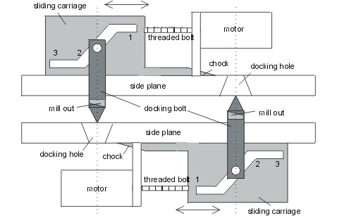
Figure 3
shows the docking mechanism. The motor moves the sliding carriage
with a threaded bolt. This causes the docking bolt to move out or into
the docking mechanism. In state 1 the docking bolt is completely inside
the mechanism. Moving from state 1 to state 2 the docking bolt moves out
and reaches the maximum outside extension but the chock is not covering
the docking hole. When the docking mechanism is in state 2 it is possible
to couple two CALINCA-vehicles. They have to take a position aligning their
docking mechanisms and must in the next step insert the docking bolt in
the docking hole of the other mechanism.
The mechanism is self-centering because the docking-bolt has a cone-top
and the docking-hole has an inside-cone. This is necessary because of the
horizontal and vertical position uncertainity of the vehicles. After insertion
of the docking-bolts both mechanisms have to transit from state 2 to state
3
which moves the chock in the mill outs of the docking bolts. The CALINCA-vehicles
are then chocked and forces can be applied to them. During releasing the
sliding carriage is moved from state 3 to state 1 simply freeing the chock
and retracting the docking bolt.
3. ELECTRONICS
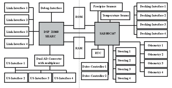
The electronics of a CALINCA-vehicle incorporates a dual processor system
to perform the necessary tasks. A floating point DSP is used mainly for
numeric and planning tasks and a microcontroller drives the actuators and
reads and converts the sensor-values. The processors are decoupled with
a dual-port-RAM. Therefore both processors have unlimited acces to their
address- and data-busses and are synchronized via interrupts (see also
figure 4).
All the electronics is integrated to a single cross-shaped 4-layer printed-circuit-board
with parts placed in surface mount technology on both sides.
3.1 SHARC digital signal processor
The ADSP-21060 SHARC from Analog Devices is used for numeric and planning
tasks of the CALINCA-vehicle. The SHARC DSP-core can calculate with 32
to 40bit floating point numbers and its internal IO-processor handles the
two serial I/O channels, the 6 linkports with 40 Mbaud each and the transfers
over the 32bit address- and the 48 bit data-busses (see also Analog Devices
1995 for more details). These features make the SHARC best suited for the
CALINCA-vehicle because the linkports are used for highspeed vehicle to
vehicle communication.
The SHARC generates the waveforms of the sonar transmitters and reads the
echo-data of the three receivers on each side. The calculation of the echo-locations,
the comparison with the map-information, the collision detection and avoidance
is done by the SHARC.
A Flash-ROM of 1Mx48bit holds the algorithms, programs and data for the
SHARC and the environment information in form of maps. It is easy to replace
them in case of program updates and changes of the map information.
In the future it is planned to integrate an IrDA compatible infrared communication
on each side for vehicle-to-vehicle communication on-the-fly, for remote
control of peripherals (like elevators) and for communication with a notebook
PC to establish a man-machine-interface. A quadruple UART will be used
to realize the IrDA communication.
Beside the processing of the sonar data the SHARC plans the path of the
CALINCA-vehicle from the building-level down to the room-level and calculates
the command values for the steering and driving motors. They are stored
in the dual-port-RAM and are retrieved by the 80C167 which writes back
the actual values of the motor-positions and the other sensors. With the
actual sensor-values the odometry calculations are executed.
3.2 Microcontroller 80C167
The main task of the Siemens 16bit microcontroller C167 is to read and
convert the sensor values, perform the control-algorithms of the 4 steering
and 2 driving motors with an overall cycle time of 2ms. The control algorithms
, programs and data are stored in the C167-internal Flash-ROM.
The encoder signals are interpolated to reach a 4 times higher resolution
and are fed to the timer-inputs of the C167. The motors are controlled
via pulse-width-modulation outputs with the PWM- or capture-compare-units
of the C167.
The C167 uses an external 12bit ADC for conversion of the four steering
and four suspension sensors (potentiometers) to have a better resolution
than its internal ADC. The internal ADC is used for monitoring the power
supply lines, motor supply currents, temperatur and humidity sensors. An
external real-time-clock (RTC) is used to store important data and to generate
wake-up interrupts for the C167.
Precipice sensors are built with infrared reflective sensors and a precipice
is detected when the light from the IR-LED is not reflected by the floor
and can thus not be detected by the IR-fototransistor. In this case an
emergency stop is invoked.
Bumpers are also added to the CALINCA-vehicle but they do not switch-off
the driving motors directly by hardware (as required by law) but via software
of the C167. This is necessary during the docking at the front and rear
sides because in the docking procedure the bumper-signals must be overridden.
3.3 Electrical docking interface
The electrical docking interface consists of a zero-force connector with
22 pins. With spring contact probes 11 pins are realized and the other
11pins are simple pads. The connector contacts the ground, the 12V and
6V charge lines as well as the 6 lines to establish a linkport connection
between SHARC´s of different vehicles.
A proximity sensor is added to control the last millimeters of the approach
and docking maneuvers.
3.4 Electrical power supply
The CALINCA-vehicle has two storage battery-subsystems. One with 12V to
supply the driving, docking and steering motors and the 6V batteries for
energizing the electronics. The capacity of the batteries are chosen in
order to guarantee a longer supply for the electronics than for the motors
to get a fail-safe behaviour of the vehicle. In case of a low motor energy
the electronic is still active and can communicate with other vehicles
to call for help. It is possible for a vehicle to tow another vehicle with
low electrical power supply. This is done by docking the two vehicles together
and the vehicle with much energy transfers its energy via the electrical
docking connector to the vehicle with low energy.
The current consumption is measured in every control cycle and thus the
amount of the remaining energy can be calculated. If the remaining energy
in the batteries is low the SHARC is informed that a recharge is necessary.
During recharge the CALINCA-vehicle docks to a recharge-terminal where
the docking connector contacts to the 12V and 6V charge line and the C167
controls the charging process of the batteries. To maximize the charging
current the SHARC, the C167 and all their peripherals are put in the idle
state. The RTC awakes the C167 in certain intervals to control the recharge
process. The charge lines are fed through the vehicle so that each vehicle
connected to a charging terminal can serve as charging terminal with its
docking interfaces.
4. NAVIGATION
A CALINCA-module navigates with internal sensors (odometry) and sensors
measuring the environment (sonar). Localization is done with odometry in
conjunction with sonar signals which are compared to stored information
about the environment (maps).
4.1 Odometry
Encoders mounted directly on each of the four wheel-axes measure the revolution-angles
of the wheels. The encoders on the free running wheels are used for more
accurate odometry purposes due to minimal slippage compared to the encoders
on the driving wheels. The signals of the encoders mounted to the driving
wheels are only used to control the motors.
The steering angles and the spring suspension movements are measured with
potentiometers which signals are fed to the external ADC of the C167. The
vertical movement of the wheel spring suspension is used to correct uneven
movements of each wheel separately (and to determine the payload weight).
A detailed description is found in Stubenvoll (1998b).
The absolute sensors for the steering position and the spring suspension
must be calibrated and the zero position must be stored permanently to
get a correct position information for the controller of the steering angles.
Calibration must be done in certain time intervals and after excessive
mechanical forces have been applied to the wheel suspension.
4.2 Sonar sensors
For our research concerning mobile transport vehicles we use a sensor,
based on the time-of-flight (TOF) of the ultrasonic signal. Additionally
by analyzing the time difference between the received signals on each receiver
3-dimensional localization of the reflecting objects can be achieved. One
transmitter with three receivers - where the transmitter also operates
as receiver - is sufficient for realization (similar to Rencken 1995).
The horizontal distance between the receivers is as large as possible to
get a higher resolution of the horizontal localization of the echo.
The sender emits an ultrasonic signal which propagates like a spherical
wave. This wave is scattered back by various objects in the enviroment
and is received by the three receivers with a time delay to the sending
signal and relative to each other. These time delays of the receiver signals
are the basis to calculate the distance, horizontal and vertical angle
of the reflector relative to the transmitter/receiver plane.
To avoid mutual disturbance of vehicles operating in the same room or very
close together the ultrasonic sending signal of each vehicle is frequency
modulated differently from each other. The receiver and the DSP of the
vehicle can then easy detect if the receiving signals have the own modulation
or was transmitted from another vehicle (see also Stubenvoll and Dimitrova
1998a).
4.3 Stored environmental information
It is necessary to provide maps of the environment for localization and
orientation of the CALINCA-vehicles. Maps available in an AutoCAD format
can be edited to classify the buildings, rooms and objects in the rooms
in terms of their function and of their sonar appearence. A number of predefined
objects are available which have to parameterized to represent the real
objects. Such predefined Objects are walls, doors, desks, stairs, elevators,
etc. where it is assumed that they move very rarely. Objects like chairs,
trash-cans, small boxes, etc. are moved very often and do not appear in
the environmental information. A collision with these easy movable objects
must be done online during movement of the CALINCA-vehicle.
The parameterized objects and the geometrical information of the AutoCAD
map of the building or room are converted by a postprocessor to a CALINCA-readable
format. These converted maps can be downloaded to the CALINCA-vehicles
by docking via linkports or via future IrDA-communication channels and
are stored in the Flash-ROM.
ACKNOWLEDGEMENT
This work was sponsored by the Austrian Science Foundation under FWF P10906-MAT.
REFERENCES
Analog Devices (1995). ADSP-2106x SHARC Users Manual
Borenstein, J., Evans, J. (1997). The OmniMate Mobile Robot - Design, Implementation,
and Experimental Results. Int. Conf. on Robotics and Automation 1997, pp
3505-3510
Eustace, D., P. Barnes, D.P., Gray, J.O. (1993). Multiple Co-operant Mobile
Robots For Unstructured Environments", Int. Conf. on Advanced Robotics
1993, pp 521-526
Hashimoto, M., Oba, F., (1993). Dynamic Control Approach for Motion Coordination
of Multiple Wheeled Mobile Robots Transporting a single Object. Int. Conf.
on Intelligent Robots and Systems 1993, pp 1944-1951
Hirose, S., Shirasu, T.,Fukushima, E.F. (1996). Proposal for cooperative
robot Gunryu composed of autonomous segments". Robotics and Autonomous
Systems Vol. 17 (1996), pp 107-118
P. Levi, et al. (1994). Architektur und Ziele der Kooperativen Mobilen
Robotersysteme Stuttgart. 10. Fachgespräch über Autonome Mobile Systeme
1994, pp 262-273
K. Ozake et al. (1993). Synchronized Motion by Multiple Mobile Robots using
Communication. Int. Conf. on Intelligent Robots and Systems 1993
Rencken, W.D., Peremans H., Möller, M. (1995). Tri-aural versus Conventional
Localization and Map Building. Int. Conf. on Intelligent Autonomous Systems
1995 IAS-4, pp 398-402
Siemens (1996). C167 Derivatives Users Manual
Stubenvoll, W., Dimitrova, T. (1998a). 3D-High Accuracy Sonar System for
Multiple Mobile Vehicles. submitted to the Int. Conf. on Robotics and Automation
1998.
Stubenvoll, W. (1998b). Odometry with increased Accuracy Using Wheel Suspension
Sensors for Correction of Uneven Movements. submitted to the 5th Int. Conf.
on Intelligent Autonomous Systems 1998
Vandorpe, J., Xu, H., van Brussel, H. (1995). Dynamic Docking Integrated
in a Navigation Architecture for the Intelligent Mobile Robto LiAS. Int.
Conf. on Intelligent Autonomous Systems 1995, pp 143-149