IV.) Using of the KEIL - µVision 2 Development Tools:
1.
Step: – Install the Tool chain - here you can download the
Keil Development Tools:
http://www.keil-compiler.de/c166/
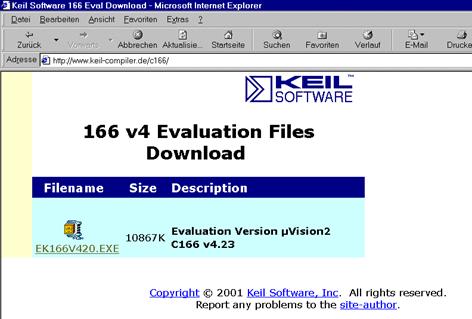
Execute
ek166v423.exe and choose C:\KeilDemo for the
installation path
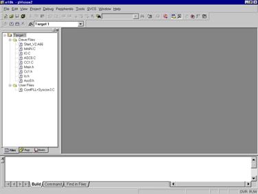
2.
Step: Start Keil µVision and
open the DAvE Project
If you see an open project – close
it: Project - Close Project
Project - Open Project
choose: C:\e10k
choose: File type: Dave
Project Files
choose:
e10k.dpt
Open
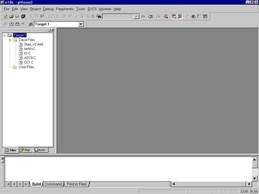
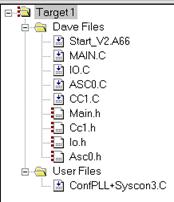
3.
Step: include the DAvE
Header Files
mouse position: Files
window: Dave Files: click right mouse button
Add Files to
Group ´Dave Files‘
input filename *.h
mark Asc0.h Cc1.h Io.h Main.h
Add
do this 4 times:
Type: choose: Custom file
OK
Close
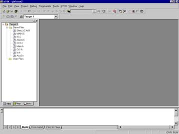
4.
Step: include the ConfPLL+Syscon3.c File
mouse position: Files
window: User Files: click right mouse button
Add Files to
Group ´User Files‘
input filename *.c
mark ConfPLL+Syscon3.c
Add
Close
5.
Step: Configure the Options
for the Header Files:
right mouse button click
Main.h
Options for File Main.h
click o Include in Target Build
click o Always Build
click o Link Publics Only
OK
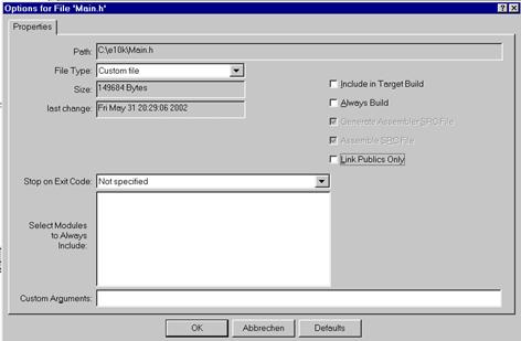
repeat this for the header files Cc1.h Io.h Asc0.h
6.
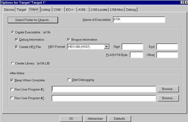
Step: Configure Compiler,
Assembler, Linker, Locater, Hex-Converter and Build – Control:
right mouse button (Files window) click Target1
Options for Target
´Target1‘
click ü Use
On-chip XRAM
External Memory #1: select
ROM, insert Start: 0x0C00000, insert Size: 0x20000
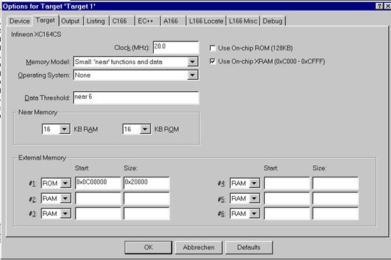
Output: click ü
Create HEX File, choose HEX Format HEX-386(H167)
Listing (do nothing)
C166 (do nothing)
EC++ (do nothing)
A166 (do nothing)
L166 Locate (do nothing)
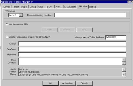
L166 Misc: insert
Interrupt Vector Table Address 0x0C00000
Debug
(do nothing)
OK
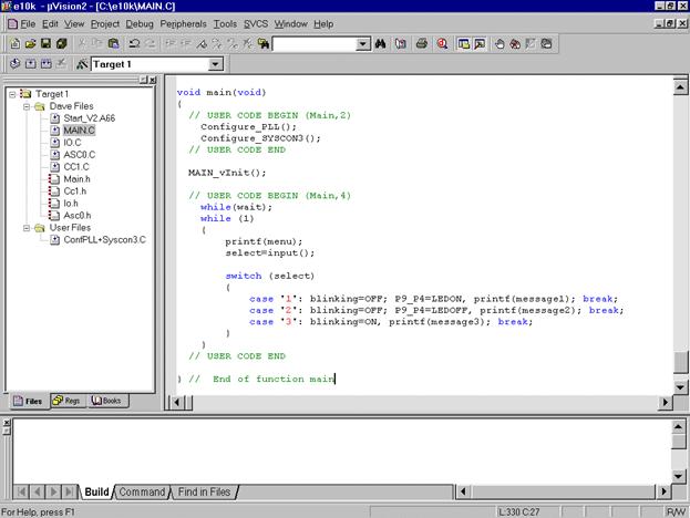
7.
Step: Insert your
application specific program:
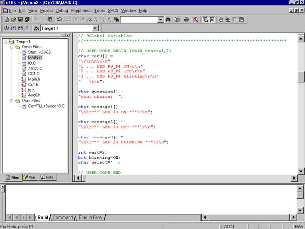
double click MAIN.C and insert Global Variables:
|
char menu[] = "\r\n\n\n\n" "1 ... LED P9_P4 ON\r\n" "2 ... LED P9_P4 OFF\r\n" "3 ... LED P9_P4 blinking\r\n" "
\r\n"; char question[] = "your choice: "; char message1[] = "\n\r*** LED is ON ***\r\n"; char message2[] = "\n\r*** LED is OFF ***\r\n"; char message3[] = "\n\r*** LED is BLINKING ***\r\n"; int wait=3; bit blinking=ON; char
select=' '; |
insert
the function input()
|
char input (void) { char
in=' '; do { printf(question); while
(!ASC0_RIC_IR) _nop_(); ASC0_RIC_IR=0; in
= ASC0_RBUF; }while
(in!='1' && in!= '2' && in != '3'); return
in; } |
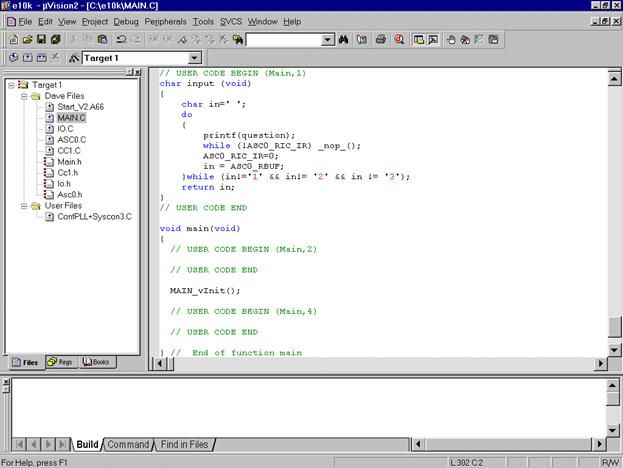
insert the
following code in the main function:
|
Configure_PLL(); Configure_SYSCON3(); |
|
while(wait); while
(1) { printf(menu); select=input(); switch
(select) { case
'1': blinking=OFF; P9_P4=LEDON, printf(message1); break; case
'2': blinking=OFF; P9_P4=LEDOFF, printf(message2); break; case
'3': blinking=ON, printf(message3); break; } } |
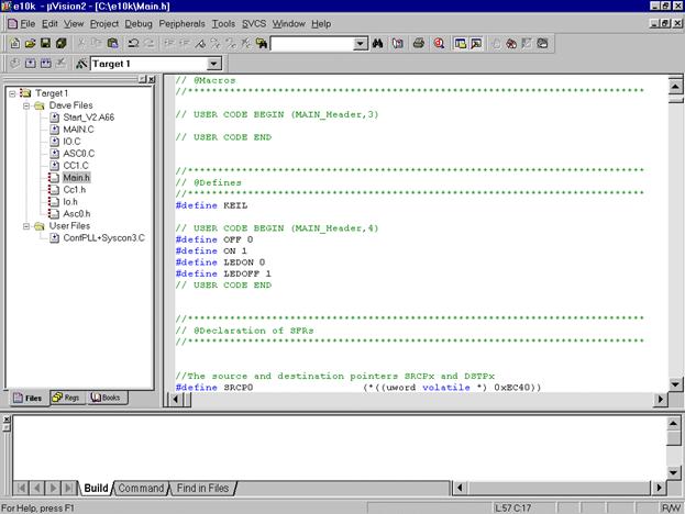
double click Main.h and insert the
following Defines:
|
#define OFF 0 #define ON 1 #define LEDON 0 #define
LEDOFF 1 |
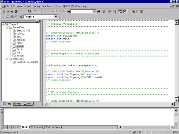
insert
Global Variables
|
extern
bit blinking; extern
int wait; |
insert
Prototypes
|
extern
void Configure_PLL (void); extern
void Configure_SYSCON3 (void); |
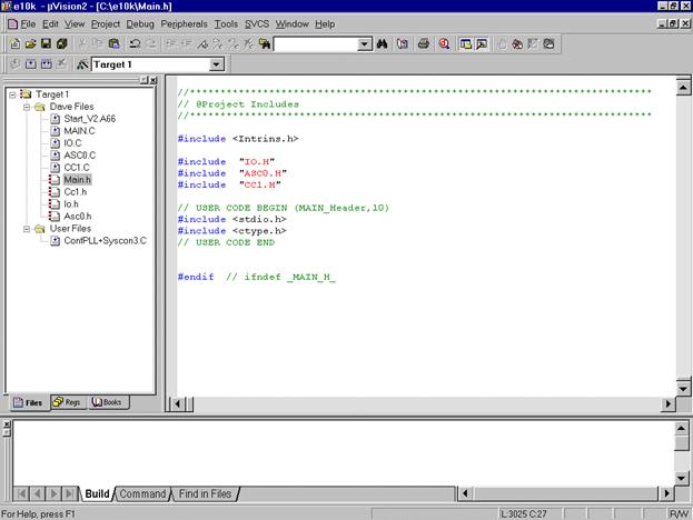
insert
Includes (for printf() )
|
#include <stdio.h> #include <ctype.h> |
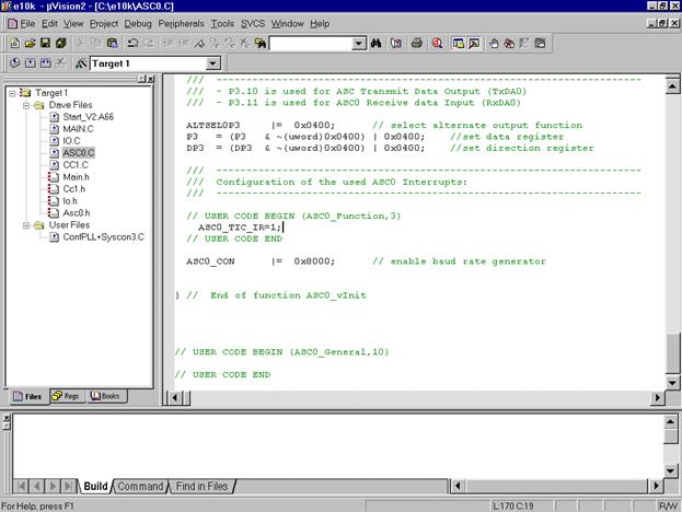
double click ASC0.C
insert in
the ASC0_vInit() function: (to start printf() )
|
ASC0_TIC_IR=1; |
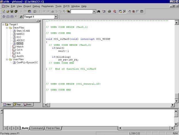
double click CC1.C
insert code
for T0 interrupt service routine:
|
if(wait) wait--; if(blinking) P9_P4=~P9_P4; |
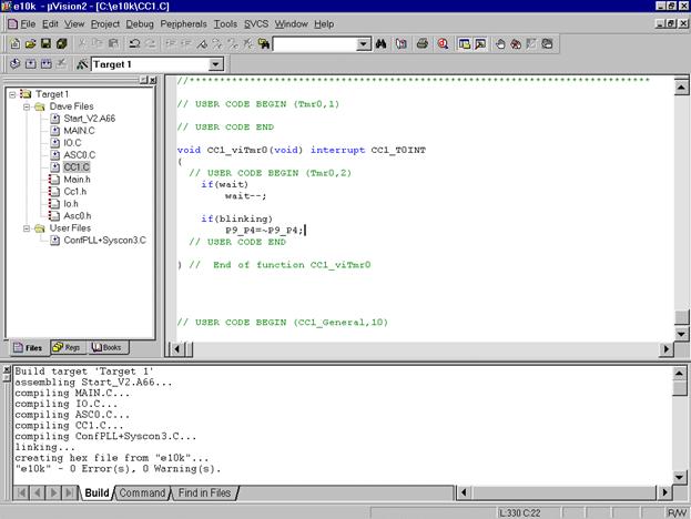
8.
Step: Generate your
application program – generate the hex file for Memtool:
Project
Rebuild all target files
Now you can close your project and µVision 2:
Project
Close Project
File
Exit
Now you can program the hex output file e10k.H86 with Memtool in the OnChipFlash (Program
Memory) of the XC164CS microcontroller.
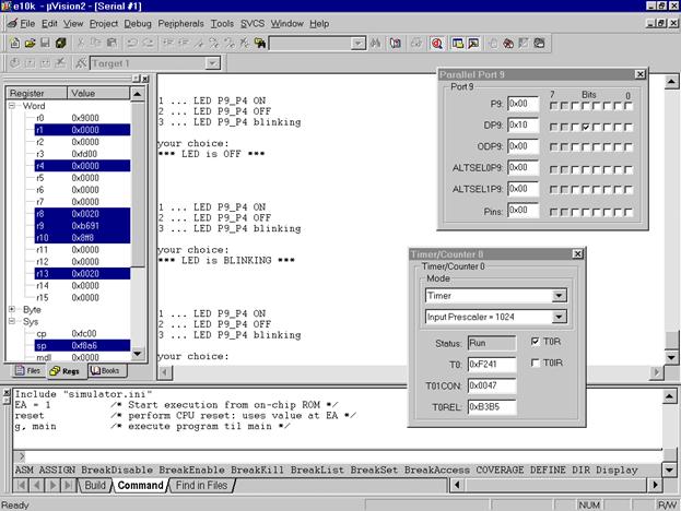
9. Step: using the simulator:
The
uVision2 simulator has a couple of VTREG's that allow you the
configuration of the
reset behaviour. These pins of the Infineon XC16x are reflected by the
following VTREGs: EA is the EA pin (0:= code fetch from
external ROM ; 1:= code fetch from on-chip ROM) ALE is the ALE pin RD is the RD pin WR is the WR pin RSTCFGP are the levels
on the configuration PINs NMIPIN is the NMI pin By default, the value
of the EA pin is set to 0 to simulate the off-chip ROM. When this VTREG is
1 at CPU reset, the uVision2 simulates on-chip ROM and the RESET vector
and interrupt vectors are at address 0xC00000. You can enable the
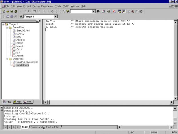
on-chip ROM behaviour as described below: 1. Create a debugger
INI file that contains the following commands: EA = 1 /* Start execution from on-chip ROM
*/ reset /* perform CPU reset: uses value
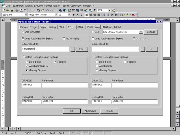
at EA */ g, main /* execute program til main */ 2. Under Options for
Target - Debug - Use Simulator, disable the option "Go till main ()" then
enter the filename for the debugger INI file you created. |
Start Keil µVision and open the Keil Project
If you see an open project – close
it: Project - Close Project
Project - Open Project
choose: C:\e10k
choose: File type: Project
Files (*.uv2)
choose: e10k.Uv2
Open
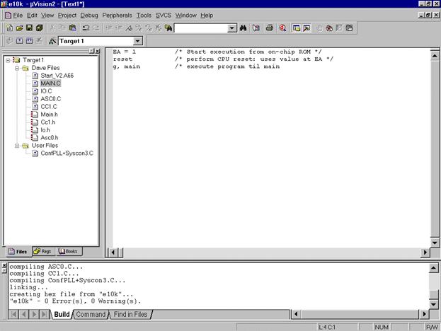
File – New
insert:
|
EA = 1 /* Start execution from on-chip ROM
*/ reset /* perform CPU reset: uses value
at EA */ g, main /* execute program til main */ |
File – Save As...
choose: C:\e10k
Dateiname/Filename: simulator.ini
Speichern/Save
... include the simulator.ini File
mouse position: Files
window: User Files: click right mouse button
Add Files to
Group ´User Files‘
input filename *.ini
mark simulator.ini
Add
choose: Type: Custom
file
OK
Close
... configure the Options for the
Simulator Ini-File:
Files window:
right mouse button click simulator.ini
Options for File
simulator.ini
click o Include in Target Build
click o Always Build
click o Link Publics Only
OK
... configure Simulator – Control:
right mouse button (Files window) click Target1
Options for Target
´Target1‘
Debug
disable Go
till main
insert
Initialization File: simulator.ini
OK
... using the simulator:
Debug
Start/Stop Debug Session
Debug
Go
View
Periodic Window Update
View
Serial Window #1
additionally – if you do not see
the Serial Window #1:
View
Serial Window #1
Peripherals
I/O-Ports
Port9
Peripherals
Capcom1 (T0,T1)
T0